 GBR
GBR A Multi-Source Inverter for Electric Drive Vehicle Applications
| ✅ Paper Type: Free Essay | ✅ Subject: Engineering |
| ✅ Wordcount: 4225 words | ✅ Published: 18th May 2020 |
Abstract
Energy storage systems in electric drive vehicles can be connected to the high voltage DC link through passive or active configurations. Passive configurations put sources in parallel without any decoupling converter among sources which increases the number of series cells in battery and Ultra-Capacitor (UC). Also, due to lack of control over UC, its stored energy cannot be utilized efficiently. Active configurations exploit DC/DC converters to control the sources separately. However, existence of DC/DC converters with bulk magnetics increases the system volume and weight, and decreases the efficiency due to inductors’ series resistances. Recently, multi-source inverters as a new concept in electric drive vehicle applications is getting attraction in both academia and industry. Reduction in the size of the battery pack and battery cell-balancing electronics, as well as higher efficiency due to single stage conversion and removal of the magnetics are the advantages of such structures. In this paper, a reconfigurable multi-source inverter with the ability of generating different combinations of the input DC sources for electric drive vehicle application is proposed.
Introduction
The global interest in energy efficient electric drive vehicles due to their superior performance over the traditional Internal Combustion Engine (ICE) cars is increasing daily. Replacing ICE cars with electric drive vehicles can save a reasonable amount of oil products as well as reduction in greenhouse gases since transportation consumes up to 63.7% of petroleum and releases 14% of the greenhouse gases worldwide [1]. Hybrid Energy Storage Systems (HESS) using battery, and Ultra-Capacitor (UC) are getting attraction in Electric Vehicles (EVs), Hybrid Electric Vehicles (HEVs), and Plug-in Hybrid Electric Vehicles (PHEVs). An HESS can be designed in two configurations, i.e. passive parallel (Fig.1 (a)) and active (Fig.1 (b)) [2]. In the primary passive parallel structure, the battery pack and UC cells are placed in parallel, which is simple to implement. However, due to high voltage ratings of the battery pack, a high number of UC cells should be placed in series to match battery pack’s voltage rating. Moreover, due to lack of a decoupling converter between the sources, effective utilization of the stored energy in UC pack is not possible. Active configurations exploit high-power DC/DC converters as the power conditioning units for voltage matching of the sources with high voltage DC bus and current control of the sources. Due to existence of magnetics, electrolytic capacitors and cooling systems in such converters, volume, weight, and the price of the system will increase [3].
|
(a) |
(b) |
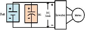
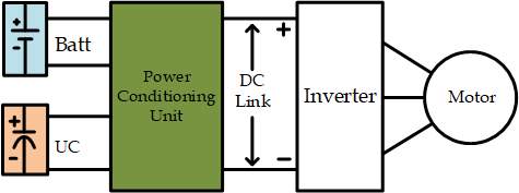
Fig.1: HESS configurations, (a) passive parallel, (b) active configuration.
A new approach towards utilization of the HESS in energy efficient vehicles, is to use multi-source inverters. A multi-source inverter is a power electronics system that connects several DC sources to the same AC output through a single stage conversion [4], [5]. Using such structure removes magnetics from the circuit and improves the overall system’s volume, weight, and efficiency. In traditional passive or active configurations the voltage at the high voltage DC link (input of the inverter) is fixed; however, in a multi-source structure this voltage is not fixed anymore. In this regards, a multi-source structure is advantageous as the switching losses of the Voltage Source Inverter (VSI) connected to a fixed high voltage DC bus are higher since switching losses of a VSI are proportional to the voltage of the DC bus [6]. The variable DC link voltage also gives the degree of freedom to costume design the voltage ratings of each source. This will decrease the voltage rating of the battery pack which leads to decrease of the cell-balancing requirements and lowers the final price of the battery pack. In [4] a multi-source inverter using T-type inverter structure has been proposed which is able to connect two DC sources to the same AC output. However, adding up the voltage sources is not possible; thus, the voltage of the main DC source should be the same as the high voltage requirements of the electric motor, which does not solve the issue of high-voltage battery packs.
If you need assistance with writing your essay, our professional essay writing service is here to help!
Essay Writing ServiceIn this paper, a three-phase bidirectional multi-source inverter for HESS applications in electric drive vehicles is proposed, which is able to add-up the DC sources. Thus, the voltage ratings of each source can be kept low. This will not only simplify the cell-balancing circuits in the battery pack, but also reduces the final price of the battery, since a governing criteria for battery price is its output voltage and power requirements [7].
Proposed Topology
Fig.2 indicates the structure of the proposed multi-source inverter. Two DC sources with different voltage ratings can be used at the DC sides. The DC source labeled with
is chosen to be a battery pack, and the second DC source labeled
can be either a battery pack or a UC bank. The choice of the second source depends on the system design and environmental criteria. For example in the extreme cold climates where temperature goes down below
, lithium-ion batteries stop working [8]. In this situation, using UC bank as a second source to warm-up the battery pack is highly recommended as UC can offer performance in wide temperature range
. Moreover, UCs can handle high surge currents due to their high specific power characteristics. Thus, during brakes, when a sudden rush of high amplitude current is released, UC bank can be used to capture the regenerated energy, while the battery pack is disconnected from the system. This will increase the life span of the battery pack as it does not have to undergo charging with high current amplitudes during brakes. Moreover, since the second source undergoes repetitive charge/discharge cycles in a driving-cycle, it is better to utilize a source that can handle repetitive charge/discharge events. Since UCs offer higher number of charge/discharge life cycles, they can be of better choice for this source. Once again it is worth mentioning that choosing the second source is a design criterion, and another battery pack instead of UC bank can be used in case longer distance coverage is of more interest.
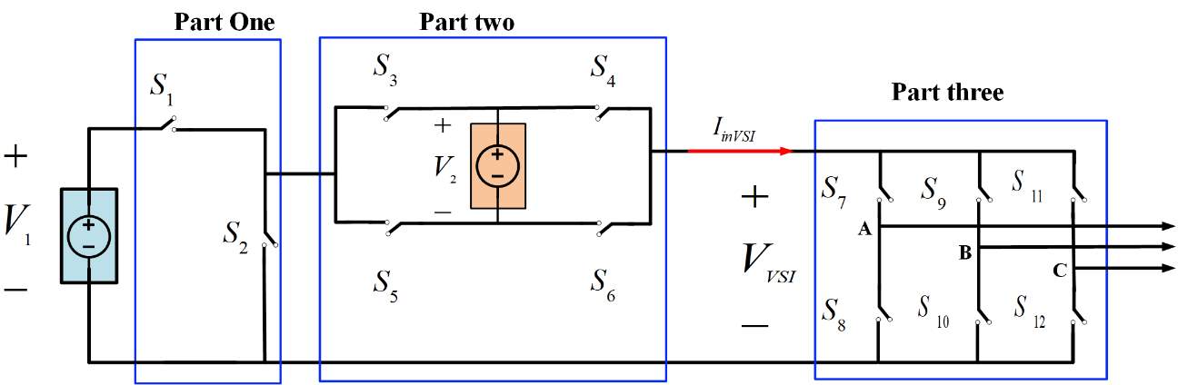
Fig.2: Proposed multi-source inverter.
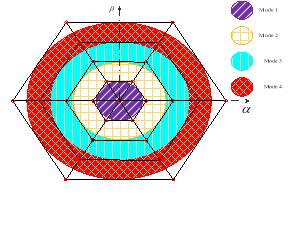
Table 1 indicates the inverter modes of operation, switching states, and
which is the variable DC input of the VSI as the third part of the inverter. Also, the effect of each switching state on the UC bank as the second source can be seen in the table. Considering that at least one of the sources is always connected to the load, the inverter can generate four voltage values at the input of the VSI, where one voltage level can be generated using two different switching commands (Mode 3). Since the VSI has eight switching states for each input voltage, the inverter has 40 switching states. Some of these switching states are redundant, which can be used for controlling purposes. Space vector representation of these switching states in
frame using (1) and (2) is shown in Fig.3.
|
|
(1) |
|
(2) |
Table 1: Switching states of the inverter and their effects on the UC pack
|
Mode |
Switching State |
|
|
|
|
|
|
|
Effect on UC pack if |
|
1 |
1 |
0 |
1 |
0 |
1 |
1 |
0 |
|
Discharge |
|
2 |
2 |
1 |
0 |
1 |
0 |
0 |
1 |
|
Charge |
|
3 |
3 |
1 |
0 |
1 |
1 |
0 |
0 |
|
Neutral |
|
|
4 |
1 |
0 |
0 |
0 |
1 |
1 |
|
Neutral |
|
4 |
5 |
1 |
0 |
0 |
1 |
1 |
0 |
|
Discharge |
Operating modes of the converter are as follows,
- Mode 1: Only the second DC source is supplying the load.
- Mode 2: The first DC source is charging the second DC source while supplying the load, as well.
- Mode 3: Only the first DC source is connected to the load.
- Mode 4: The input voltage of the VSI is equal to the summation of both voltage sources and both sources are being discharged in the load.
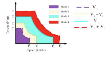 Fig.4 indicates the simplified torque-speed characteristics of the electric motors for different input voltage values [9], [10]. As it can be seen, by changing the input voltage of the electric motor, different torque-speed characteristics can be obtained. In this regard, each source can be designed such that it matches the electric motor’s voltage rating while its output voltage is kept as low as possible. This will decrease the cell-balancing requirements of the sources. For instance in mode 4, when the higher toque values or higher speed regions are required, two DC voltage sources are put in series to generate a high voltage amplitude at the input side of the VSI. In this way, the high voltage requirements of the electric motor during peak powers can be met while a battery pack with lower voltage rating is used. Also, the input power of the electric motor comes from the inverter and the input power of the inverter is the product of its input voltage and current as described by (3). During peak power requirements such as hill climbing or acceleration events, this peak power can be provided in two ways, i.e., increase of current while the voltage is constant, or increase of voltage while keeping the current constant. In stiff DC link structures, the increase of current was used to compensate for high power requirements. With variable DC link structures, current increase can be maintained in a certain level during peak power requirements with increment of the DC link voltage. This will increase battery pack’s life span as discharging battery with high current amplitudes
 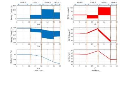 degrades its life.
|
|
(3) |
Simulation and Experimental Results
Matlab/Simulink was used to assess the performance of the proposed inverter. The voltage of the battery pack is set to be 300 V and its initial SOC is 80%. The UC bank has a rated voltage of 100V, capacitance of 84 F, and initial SOC of 90%. Space Vector Modulation (SVM) is used to control the switching actions of the inverter. Fig.5 indicates the current, voltage, and SOC of the battery pack, and UC bank, during each mode of operation.
Our academic experts are ready and waiting to assist with any writing project you may have. From simple essay plans, through to full dissertations, you can guarantee we have a service perfectly matched to your needs.
View our servicesIn mode 1, only the UC is supplying the load; thus, battery current is zero and its SOC is not changing. In mode 2 UC is being charged by the battery and its SOC is increasing. In mode 4 both of the sources are supplying the load and their SOCs are decreasing. In mode 3, only battery is supplying the load. Consequently, UC current is zero, and its SOC and voltage are constant. Fig.6 is the simulation results of the inverter output voltage and current. Also, load current and line voltage during transition from mode 1 to mode 2 can be seen. Experimental results of a scaled down lab prototype is shown in Fig.7 for line voltage and three phase load currents. As it can be seen, experiments are in agree with simulations and theory.
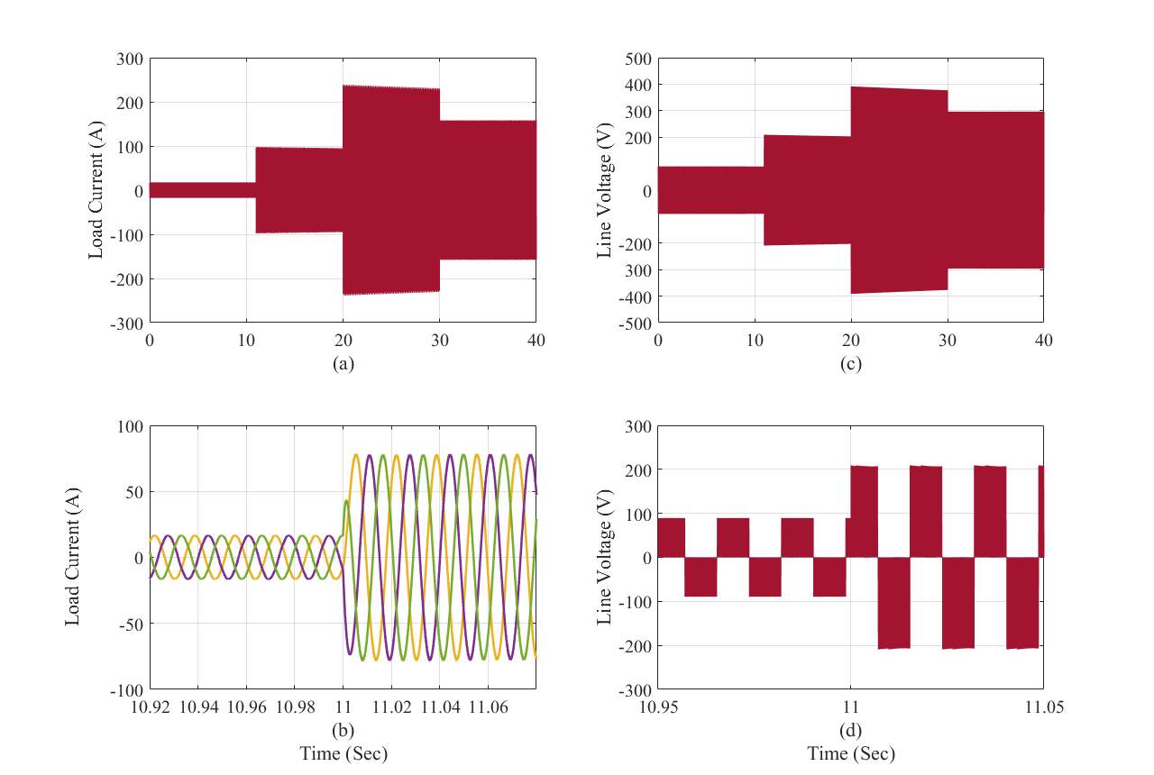
Fig.6: Simulation results of the inverter current and voltage. (a) Load current, (b) Load current during transition from mode 1 to mode 2, (c) Line voltage, (d) Line voltage during transition from mode 1 to mode 2.
|
(a) |
(b) |
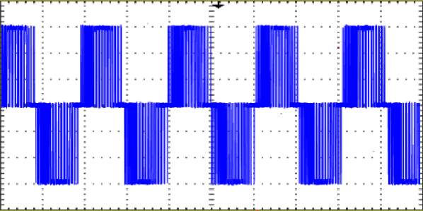
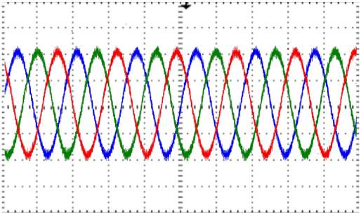
Fig.7: Experimental Results. (a) Line Voltage, (b) Load Current.
Conclusion and Future Work
A new structure for Hybrid Energy Storage Systems is proposed in this paper, which removes the need for DC/DC converters. Since there is no magnetics in the circuit, the structure can be compact and light which is of high interest for electric drive vehicles. Operating modes of the proposed multi-source inverter are described, and simulation and experimental results are carried out as a proof of the concept. Control over the stored energy of each source is possible and the sources can exchange energy as well. Space Vector Modulation is used to control the switching actions of the inverter. In the full paper, detailed description of the inverter’s operation, as well as modulating technique with more simulation and experimental results will be provided.
REFERENCES
[1] Akimoto K., F. Sano, A. Hayashi, T. Homma, J. Oda, K. Wada, M. Nagashima, K. Tokushige, and T. Tomoda, “Consistent assessments of pathways toward sustainable development and climate stabilization”, Natural Resources Forum 36, 2012.
[2] S. M. Lukic, S. G. Wirasingha, F. Rodriguez, J. Cao and A. Emadi, “Power Management of an Ultracapacitor/Battery Hybrid Energy Storage System in an HEV,” Proc. of the 2006 IEEE Vehicle Power and Propulsion Conference, Windsor, 2006, pp. 1-6.
[3] A. Khaligh and Z. Li, “Battery, ultracapacitor, fuel cell, and hybrid energy storage systems for electric, hybrid electric, fuel cell, and plugin hybrid electric vehicles: State of the art,” IEEE Trans. Veh. Technol., vol. 59, no. 6, pp. 2806–2814, Jul. 2010.
[4] L. Dorn-Gomba, P. Magne, B. Danen and A. Emadi, “On the Concept of the Multi-Source Inverter for Hybrid Electric Vehicle Powertrains,” in IEEE Transactions on Power Electronics, available at “ http://ieeexplore.ieee.org/abstract/document/8078206/”.
[5] A. Emadi and P. Magne, “Power converter,” Apr. 25 2014, CA Patent App. CA 2,831,252.
[6] F. Z. Peng, J.-S. Lai, J. W. McKeever, and J. VanCoevering, “A multilevel voltage-source inverter with separate dc sources for static var generation,” IEEE Transactions on Industry Applications, vol. 32, no. 5, pp. 1130–1138, Sep 1996
[7] E. Chemali and A. Emadi, “On the concept of a novel Reconfigurable Multi-Source Inverter,” 2017 IEEE Transportation Electrification Conference and Expo (ITEC), Chicago, IL, 2017, pp. 707-713.
[8] T.B. Reddy, “Linden’s Handbook of Batteries (Fourth Edition),” published by McGraw-Hill, 2011.
[9] T. A. Burress, S. L. Campbell, C. L. Coomer, C. W. Ayers, A. A. Wereszczak, J. P. Cunningham, L. D. Marlino, L. E. Seiber, and H. T. Lin, “Evaluation of the 2010 Toyota Prius hybrid synergy drive system,” Oak Ridge National Laboratory, Tech. Rep. ORNL/TM-2010/253, Jan 2008.
[10] M. Ehsani, Y. Gao, A. Emadi, “Modern Electric, Hybrid Electric, and Fuel Cell Vehicles Fundamentals, Theory, and Design,” Second Edition, CRC Press, New York, 2010.
Cite This Work
To export a reference to this article please select a referencing stye below:
Related Services
View all


DMCA / Removal Request
If you are the original writer of this essay and no longer wish to have your work published on UKEssays.com then please:


