 GBR
GBR Digital Manufacture 5 –Assignment: Evaluation of Digital Manufacturing Tools
| ✅ Paper Type: Free Essay | ✅ Subject: Design |
| ✅ Wordcount: 6006 words | ✅ Published: 23rd Sep 2019 |
Digital Manufacture 5 –Assignment: Evaluation of Digital Manufacturing Tools
1 Introduction
2 Optimisation and generative Design (Limit to 1000 words)
2.1 Goal seeking
Goal seeking is a function embedded into CAD software such as Solid Edge. The goal seeking function essentially automates engineering calculations without the need to rearrange equations or even may remove the need to develop equations (insert Citation). The goal seeking function assumes the part the user has uploaded on CAD has a defined geometry, area and volume, then the user simply dimension’s the part and the goal seeking function finds the unknown parameter. Strategies such as Hill climbing is used in the goal seeking process for certain CAD software. Hill climbing works by initially sampling a point at random, then taking a few other samples around the initial sample. The algorithm then works out the largest value and moves to that point, then the process is repeated till the highest sampling point is found, which theoretically is the maximum value (top of the hill). The algorithm operates on the various engineering formula and dimensions, once the algorithm finds the maximum value it will update the user with certain part information such as variables and physical properties.
 2.1.1 Goal seeking example:
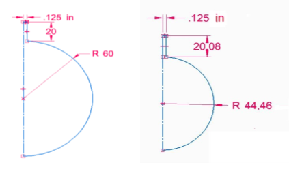
The example above shows the goal seeking function in use. The two, 2-D sketches represent a 3-D part which is a dummy mass made out of aluminium. The objective was to make sure the part on the lefts mass, is 800g. Thus, after the goal seeking function was used, the part on the right was created with the unknown parameters of radius shown to reduce to 44.46mm.
If you need assistance with writing your essay, our professional essay writing service is here to help!
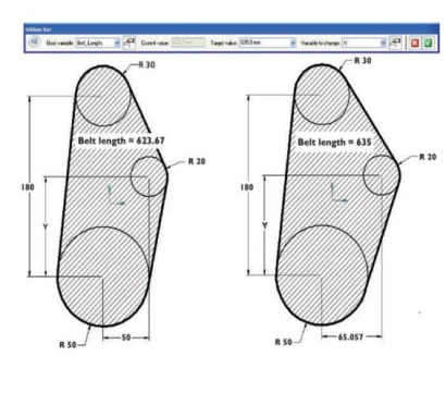
Essay Writing ServiceFigure 2 is a goal seeking example shown in a paper written by Siemens (insert citation). The objective was to increase a pulleys belt length from 623.67mm to 635mm, the specific value that was found when the belt length increased, was the bottom wheel. Its dimension increased from 50mm to 65.057mm with the rest of the pulley’s parts keeping the same dimensions.
2.2 Basic Optimisation Strategy
2.2.1 What is meant by optimisation and overview of area?
Optimisation in the computer aided design context refers to, using defined search algorithms in order search the design space of a part or an assembly on CAD. Once the algorithms have finished searching the space, certain design variables are altered by the algorithms in order to obtain the optimum results (insert citation).
2.2.2 What is unconstrained/constrained optimisation?
The constrained optimization problem is one where you might want to maximise a certain evaluation/objective function which might be some kind of multi-variable function i.e.
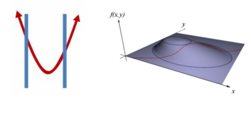
which must satisfy one or more equations as shown in equation 1. Which then you are subjected to a certain constrains shown in equations 2 and 3 (insert Citation). These constraints are a hard limit that is placed on the value of a variable that prevents us from going in certain directions. Figure 2, clearly shows a visual representation of a 2-D function (on the left) and a 3-D function (on the right) that has been subjected by constrains.
An example mathematical description of a constrained problem is shown below:
Maximise:
Subject to constraints:
The various types of constrained algorithms that are useful are as follows: Exhaustive search, Hill climbing, Gradient approaches, simulated annealing, Genetic algorithms and many other algorithms. However, simulated annealing and genetic algorithms were first constructed for unconstrained optimization which was then adapted for constrained optimization.
Unconstrained optimisation means, find x and y such that
is a maximum, there is no restriction on the range of the function. In some problems unconstrained optimisation problems appear directly, however in some cases unconstrained optimisation arise as a result of the reformation of constrained optimisation (insert Citation).
2.3 Examples of optimisation
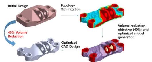
Figure () shows the optimization process taking place with an initial design that has gone through topological optimisation. A linear static analysis is conducted on the initial design in-order to find the various stresses and displacements. The software then finds the areas where the loads are the highest, which is then means more material is required and the areas where the load are low, less material will be used. After the optimization process it can be clearly seen that 40% of the volume is reduced as shown on figure (), producing a lighter, stronger and more aesthetically pleasing design.
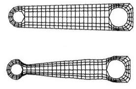
The picture on Figure () shows optimization process taking place with an initial design of a torque arm that has been optimized by the finite-element based optimization process. In this case boundary conditions have been applied at the holes of the torque arm and a torsional force as well. The computer then uses an integrated optimiser with the unconstrained algorithms in order to find the optimized part.
2.3 Generative Design
Generative design uses Darwinian Theory of natural selection, breeding and mutation in order to optimize a design and produce variants of a design. A designer or an engineer will have to specify certain input design parameters i.e. weight, stiffness, cost constrains etc. Into the CAD software, then the software explores all the possible permutations by using cloud computing. When the software is on the cloud it looks through all the possible options by testing configuration and learning from each iteration, in order to find out what works and what doesn’t (insert Citation). The testing and learning process the software conducts is possible by the use of a search algorithm called the genetic algorithm. The genetic algorithm uses the principle of Darwinian Theory in order to find the fittest individuals. Figure () shown below shows the basic model used for a Genetic Algorithm.
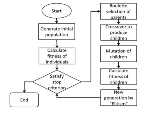
The algorithm starts by generating an initial population which is a set of designs, different approaches are used in order to generate the set of designs. One example is randomly selecting designs from the design space. Then the algorithm starts to rank these initial designs, it makes sure that the best designs are chosen and then a mating pool is created which encloses the best designs. Then the algorithm recombines these designs in order to create new offspring from the randomly selected parents that were chosen from the mating pool. The child produced is joined to the next generation. Lastly, the mutation takes place where missing information which the child might not have received will be added into the gene pool. With the mutation taking place the algorithm can finally converge towards a correct solution, where the best of best in each generation and design is ranked and scored which shows that with each generation the design is improved. Then a set of the best designs will be shown to the user at the end of generative design process.
The limitation of Generative Design (What it can and can’t do)
Generative design improves an engineer’s design by using cloud computing and machine learning in order to find a large set of solutions. Its purpose is not to eliminate the engineer, but more to expand the known set of solutions that the engineer has found without using the software. However, there are some limitation to generative design especially in industry
3 Reverse Engineering and 3-D Scanning (1000 words)
Understanding of different 3D file formats?
intro and some examples of file types (voxels, triangles, surfaces)
3.1 3-D file formats (2 marks)
In the world of 3-D scanning, data is normally represented as a point cloud with millions of points arranged in an un-orderly fashion which is stored in a file. It is almost impossible to create a perfect 3-D mesh of a model due to problems such as clutter, reflectivity and areas missed, which makes it difficult to obtain a complete spherical map of an object (insert citation). In order to patch the areas of the model that are incomplete or exists as problem areas, it would be necessary to stitch several surface regions to form a 3-D triangle mesh model.
One of the most common formats used to store 3-D data, is the STL file format. It has been established for almost two decades, as the industry standard for supplying data amongst design programs and other specific design software such as 3-D printing or additive manufacture software (insert citation). The STL file encloses only data about a surface mesh but doesn’t contain information about texture, colour, material and other important properties. The surface mesh is made out of an unordered list of triangles, for every triangle 12 floating point numbers that represents it. For a 3D surface normal there are three coordinates that is used to represent the triangle. This means that each vertex that is adjoining with the other triangles has to be repeated multiple times which leads to inconsistencies, leaks and small rounding errors with the vertices that don’t exactly line-up.
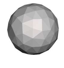
Figure () shown on the left clearly shows a mesh of a ball that has been saved in a an STL file. The triangles representing each surface normal is shown to cover the whole ball, as rounding errors of the vertices clearly dominant.
3. 2 Advantages and Disadvantages of Mesh models (2 marks)
???
3.3 Boundary Representation (B-Rep) (1 mark)
 Boundary representation is a fundamental data structure that is widely used in the world of geometric modelling. The underlying concept for the boundary representation was developed independently by Ian braid and Bruce Vanguard at computer Vision (insert citation).
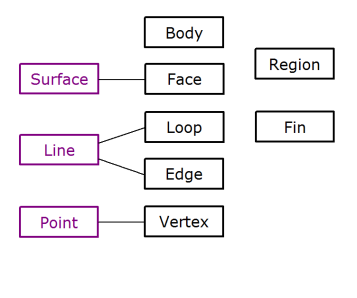
The basic intuition of B-Rep is shown in the figure (), which outlines the flow of how the B-Rep works. A solid object has surfaces or faces that forms its outer boundary. Each face has a set of boundary curves called edges which define its material region. An edge has end points and vertices that define its outer limits. This allows the B-Rep to treat a collection of surfaces as a single object.
B-rep has many advantages such as its ease when converting a B-Rep model into a wireframe model, due to the boundary’s definition being almost identical to the wireframes. However, the main advantage is having the ability to construct solid models from unusual shapes, these shapes pose a major problem when using primitives to build them (insert ct).
3.4 Features (2 marks)
??
3.5 3-D Scanning Process (2 marks)
3-D scanning is a widely used method in design and engineering in order to analyse a physical object, with the end goal being collecting data of the shape of the object. After the collation of data, 3-D models may be constructed. Its applications in manufacturing is quite dominant with areas such as reverse engineering, Quality assurance, Design Process, Medical equipment and As-built/as-is- modelling.
 If we take the case of medical equipment, it can be seen in the figure on the left that a 3-D scan is being made of a person’s leg. The 3-D scan allows for custom-fit parts to the customer, thus the patient will receive a prosthetic that is custom fit, without the need of buying a general prosthetic leg and adjusting it to fit the person’s leg.
There are two main types of 3-D scanning technologies: Contact and non-contact. Contact technologies such as CMM (coordinate measuring machines) are very precise and accurate scanning technologies, this is because the scanning device is in direct contact with the part .100’000’s of data points are being generated with the accuracy being down to the micron level, however this method maybe very accurate but the entire process is extremely slow. Non–contact technologies such as structure light, time of flight and triangulation is used to scan parts and assemblies. If we take the example of structured light, it projects a stripped pattern on the object in either the visual range of the infrared. The two camera’s look at the stripped pattern, which essentially allows the camera’s to pick up complex images, such as features and edges by using complex algorithms. Since the various features can be recognised in the two camera’s the depth of the object can be inferred. The problems with non-contact methods is some features may be not recognised …. (Talk about reflectivity, clutter and some areas’ that are missed)
 3.6 Comparison to other methods (2 marks)
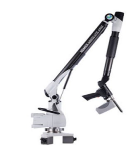
Methods of measuring geometry, such as using calipers and coordinate measurement will be compared in this section with respect to Non-contact 3-D scanners. Calipers are quite prone to errors, a reference line of a particular measuring system introduces errors, when it does not lie along the same line as the dimension that is being measured. Many times, the scales on the caliper are not in line with either the measuring faces or contacts. This means the caliper will be prone to moving around i.e. shifting and wiggling, which increases error in the measurements. 3-D scanning eliminates the problems or position and stability as robotic arm scanners as shown in the image on the right effectively provides stability as the arm will be bolted to a stable surface will not be susceptible to vibrations (insert Citation).
The areas where Non- contact Scanning processes beat coordinate measuring tools are speed, automation and cost. Laser scanners can detect almost hundred of thousand of points or even millions of points per second, however the real question is the time that is needed to measure the quality of the part not so much the speed.
3.7 Complexity v accuracy (2 marks)
Trade off between methods
3.8 Context of Reverse engineering (2 marks)
Reverse engineering in the context of design, is understanding the shape of a physical object by deconstructing it for the purpose of understanding its design, manufacture or function. In the world of design an object would typically be reverse engineered in order to be exploited in CAD (IC). The main uses of reverse engineering in the design and engineering world is as follows:
- Understanding how a product works
- Improve a part or an assembly
- Change an out-of-date part
- Duplicate or copy a competitor
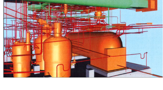 If a part is broken or damaged and can’t be traced back, reverse engineering can help find the part or obtain the design of the part. Augmented reality is a reverse engineering tool that has been opted in the oil and gas and nuclear industries. In the nuclear industry companies will put their employees through augmented reality in order to train them to decommission something before the attempt to the real thing, which reduces disposal cost. The image below shows a scan of a site at Sellafield where the company has scanned the site and then made their employees use augmented reality in order to have a sense of the area and make sure the procedure is right for a post operational clean out.
In the oil and gas industry companies will use augmented reality so that they can train their employees before they go on sight and fix things, which reduces service costs.
(Talk about file retrieval, new models) and legal aspects
4.0 Additive Manufacturing (AM) (1000 words)
4.1 Introduction to Additive Manufacturing (1mark)
Additive manufacturing or 3-D printing has been described as revolutionizing product development and manufacturing, with some people going as far as saying “we are experiencing a technological revolution” – David Rosen. AM refers to a process of creating parts by adding material in layers. Every individual layer is a thin cross-section of a particular part that has been obtained from the CAD data, which has been supplied to the 3-D printer. Since each layer is printed with a specific thickness, the resulting part will be an approximation of the original part. Thus, the thinner the layers are, the closer the printed part will be to the original (Insert Citation). The materials used in AM are mainly thermoplastics such as PLA, ABS, Nylon, TPU and PVA, these materials have various mechanical properties and differ in costs. The type of material used will depend on the type of application and cost-constraints.
4.2 When to use additive manufacture (Benefits and Drawbacks) (2 marks)
The start to end process of designing and manufacturing parts have most definitely been benefitted by AM. Factors such as cost, design, speed and quality are the main areas where AM have an advantage vs traditional manufacturing. Many stages of manufacturing have been eliminated, as traditional manufacturing processes needed multiple and iterative stages in-order to create a part. Also, as the number of features increases the complexity of the part does as well. Which AM has no problem with dealing with, regardless of the complexity of the part, the manufacturing process can be performed in a single step (IC). This single step manufacturing process of AM compared to other traditional methods is much faster as lesser time is taken due to the compressed design cycles in AM.
(Talk about lighter and smaller amount of waste)
The recent advances in additive manufacturing technology has allowed for the production of complex parts in the small, medium and large scales. In spite of additive manufacturing being able to produce medium and large parts many industries such as aerospace, automotive, oil and gas etc. use additive manufacturing to produce smaller, core components. This is due to AM processes being able to produce high level of precision and flexibility when manufacturing small components. Another factor in why companies produce smaller parts rather than medium or large is due to High costs per part at scale, thus producing smaller components is more cost effective as larger parts use up more material and energy which increases costs.
4.3 Additive Manufacture Process (2 marks)
This section provides a deeper understanding of five out of the seven AM processes and discusses the benefits of each process. The five additive process that will be discussed are as follows:
- Vat photopolymerization
- Powder Bed Fusion
- Material Extrusion
- Material Jetting
- Binder Jetting
The Vat photopolymerization process uses materials such as radiation-curable resins or photopolymers. Ultraviolet radiation coupled with visible light is used in order to cure the materials. The reaction that occurs is called photopolymerization whereby the materials undergo a chemical reaction, as a result the material becomes solid.
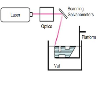
The figure above shows schematic representation of a Laser scan Vat Polymerization, it can be seen that the scan produces solid parts by solidifying the liquid photopolymer resin using an UV laser. The physical part is made by staking slices on top of each other. When each slice is completed, the platform will be lowered, then the surface of the slice will be coated into a vat of resin. This process will be repeated till the part is completed. The advantages of this process are that it produces very accurate and smooth parts at a relatively high speed, however the parts are quite brittle and thus are not used in applications that require strong structural properties.
Our academic experts are ready and waiting to assist with any writing project you may have. From simple essay plans, through to full dissertations, you can guarantee we have a service perfectly matched to your needs.
View our servicesPower Bed fusion processes works by using a thermal source, in this case a laser is used in-order to promote fusion between the particles of powder. The power is normally spread across the whole build platform and then the laser heats certain areas of the powder which solidifies the powder. A lot of the powder in the process remains used and can be recycled for the next fusion process.
Material Extrusion
4.4 Examples of AM in engineering (2 marks)
4.5 Fused deposition modelling (FDM) 3D printing in detail (2 marks)
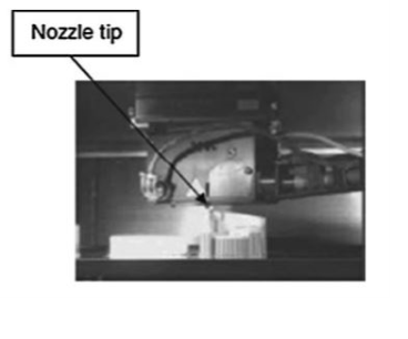
Fused deposition modelling is the most common extrusion-based AM technology in the market. The way FDM works is, it uses a heating chamber which liquefies the polymer, this polymer would have been fed into the FDM system as a filament. An extrusion pressure is generated in the chamber when the filament is being pushed out to produce a layer on a build plate, a tractor wheel arrangement allows for this to happen. After ever layer is produced, the build plate lowers and the next layer is built up till the full part if manufactured. This process is shown in the figure below.
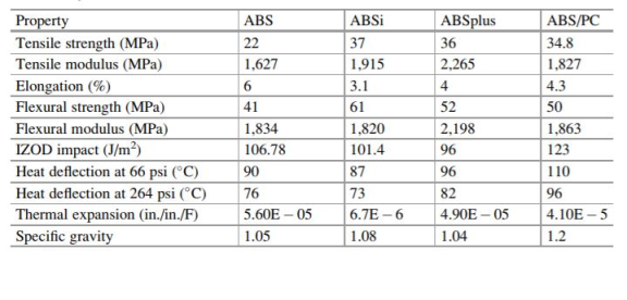 The most commonly used material in FDM is the ABS material, there are other variation of ABS materials such as ABSi, ABSplus and ABS/PC which are widely available. The tensile properties of these material vary, as the user can choose which kind of material, they would like depending of the structural loads the part will be experiencing. ABSi however provides a translucent effect which can add to the aesthetic of manufactured part. ABSi and ABSplus both have high tensile strengths of between 36Mpa to 37Mpa and also have higher tensile modulus and thus can be used for parts that are experience heavy loads. ABS by itself has the highest elongation % which is suitable for application that might experience loads over its Ultimate tensile strength.
 4.6 FDM design consideration (3 marks)
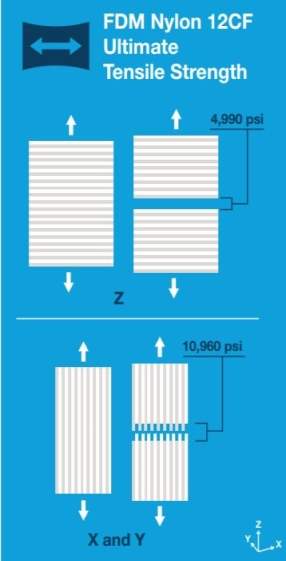
One of the main design considerations users should take when manufacturing a part using FDM is the anisotropic part strength. Anisotropic part strength occurs in FDM due to the layer-by-layer deposition of the system. This means the tensile strength of the material is stronger in the x-y direction compared to the y-direction. To avoid this issue, build orientation, part geometry and pre-processing techniques can be used to mitigate these problems. AM software provides the user with various strength value for the different orientations.
This is illustration of stronger tensile strength in the x-y direction and weaker strength on the y-direction is shown on the right.
In order to mitigate applied tension, compression, bending, shear and torsional loadings for FDM tooling, the shortest possible load part should be taken. The AM software contains tools such as topology optimization which gives the user information about how the material will be distributed.
Factors such as creep can affect the manufacture of parts in AM, thus one way to deal with this problem is by designing mounting and wear points, by either using ceramic or metal inserts. These inserts will help with the part from dynamic overload or from high static forces (IC).
Figure 13: Anisotropy shows the z plane is the weakest plane
In order to increase the time to fabricate a part in AM, there are few design considerations that can assist to this problem. Orient the tool to extrude most material in the x-y direction, this increases the speed of manufacturing as well as the strength of the part. Having support material which are require to mitigate overhang, by using angles less than 45
from the build plate, which support both the interior and exterior features will increase fabrication time.
 4.7 From CAD to Print (3 marks)
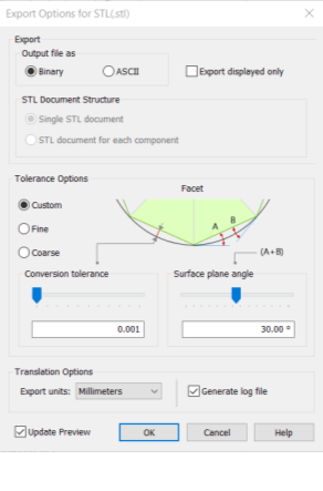
The first step to converting a CAD file to be 3-D printed is by preparing the CAD model to be exported into to a STL mesh. This is because STL is the most common file type and is recognised by most 3-D printing software. In CAD software such as Solid Edge, users will receive an exporting tool bar as shown in figure (). The tolerance options are given with the options of choosing custom, fine or course. This of course refers to the resolution of the surface mesh, choosing the fine option over the course option means your STL file will have a finer mesh and thus the resolution and surfacing of the model will be better.
Once the CAD model has been converted into an STL file the model will have to be imported into a slicing software such as Utilmaker Cura. The software will then proceed to slice the 3-D model. The 3-D model will be sliced into smaller 2-D profiles and the software will recognise and generate certain commands in order to control the printing head so that it can print the individual slices layer by layer.
After the software slices the 3-D model the user then has a couple of options to tweak the printer parameters. These options include the speed of manufacture, quality, support, Infill, shell and other important parameters.
https://ultimaker.com/en/resources/52343-shell
Communication Design Intent
(Brief intro)
5.1 The significance of standards (2 marks)
Where and how are they implemented, contractual
Standards play an important part in the industrial process, by providing information that helps compete and produce a cost-effective production. Standards are the defining tool that provide essential information of materials, products and various procedures in clear, precise and authoritative way. It captures product and performance specifications, measurements, testing methods and other important information (IC).
The are various forms of standards that exits all around the world. A lot of countries have their own standard which they use for specification and technical product documentation. As global trade as been soaring in the last few decades countries are starting to agree to a common standard. Many standard institutes small and large worldwide, are now part of the International Organizations for standardization (ISO). ISO objective is to develop on voluntary technical standards, this allows for the manufacturing and supply for products much more efficient, safer and cleaner.
References
- Cyprien. How to Reduce CAD Design Cost using simulation ? 4 October 2014.
- D, Jonathan Hiller, and Hod Lipson. “STL 2.0 : a proposal for a universal multi-material additive manufacturing file format.” In Proceedings of the Solid Freeform Fabrication Symposium, vol. 3, pp. 266-278. 2009. Proposal, New York: Cornell University, 2009.
- Gibson, Ian, David Rosen, and Brent Stucker. Additive Manufacturing Technologies. Textbook, New York: Springer Science+Business, 2015.
- Hsu, Yeh Liang. Solid modelling techniques and boundary representation. 11 october 2008.
- J, Nocedal, and S J Wright. Numerical Optimization. New York, 1999.
- McHenry, Kenton, and Peter Bajcsy. “An overview of 3d data content, file formats and viewers.” National Center for Supercomputing Applications 1205 (2008): 22. Urbana: Nation Center for Supercomputing Application, 2008.
- Mill, Frank. Optimization and Generative Design. Edinburgh : University of Edinburgh , 2018.
- Nagy, Danil. “The problem of learning.” Generative Design, 2017.
- Pearson, John. Using Goal Seek to aid in model design in Solid Edge. 30 July 2012.
- Software, Siemens PLM. “Goal Seeking in Solid Edge.” A white paper , n.d.
- Stanford University . Introduction to Constrained Opimization. n.d.
- Stratasys. “Design Considerations for FDM Additive Manufacturing Tooling.” Design guide, 2018.
- T, haftka Raphael, and V Ramana Grandhi. “Structural shape optimization—a survey.” Computer methods in applied mechanics and engineering 57.1 (1986): 91-106. Survey, Dayton: Elsevier Science Publishers , 1986.
- Ultimaker. “Setting for Ultimaker.” Ultimaker.com. 2018. https://ultimaker.com/en/resources/52343-shell.
- Varady, Tamas, Ralph R Martin, and Jordan Cox. “Reverse engineering of geometric models—an introduction.” Computer-aided design 29.4 (1997): 255-268. Research paper , Elseviar Science , 1997.
Cite This Work
To export a reference to this article please select a referencing stye below:
Related Services
View all


DMCA / Removal Request
If you are the original writer of this essay and no longer wish to have your work published on UKEssays.com then please:


