 GBR
GBR Stages of Software Engineering Concept and Implementation
| ✅ Paper Type: Free Essay | ✅ Subject: Computer Science |
| ✅ Wordcount: 4161 words | ✅ Published: 18th May 2020 |
Contents
1.1 The software engineering concept and how it differs from programming
1.2 The concept of the software development lifecycle (SDLC) and its stages
1.3 Software implementation and its management via software metrics
Task 3: Illustrate and compare
Task 4: Critically evaluate two implementation languages
Task 1: Explain and Describe
1.1 The software engineering concept and how it differs from programming
If you need assistance with writing your essay, our professional essay writing service is here to help!
Essay Writing Service
1.2 The concept of the software development lifecycle (SDLC) and its stages
SDLC is a systematic methodology for developing software, which ensures the consistency, accuracy, quality and correctness of the software. The aim of SDLC is to develop high-quality product or software that meets customer or user requirements and expectations. The development of the software should be completely done in pre-defined cost and time frame. It comprises of details about the software that how to schedule, plan, develop and maintain software. There are different phases of SDLC, each phase has different process, and their outcomes are pass into next phase.
Phases of SDLC are as follows;
• Requirement Analysis – in this stage the important information is gathered from the customer to develop a product that requires their expectations.
• System Design – in this stage it is required to gather the software requirements specification documents in as an input, and the architecture that is used for applying system development is resultant.
• Implementation – this starts as soon as the developer has gotten the design documents.
• System Testing – the testing starts when the coding is complete and when the modules are available for testing. During this phase the software is tested and if any defects are found they will be noted and are assigned to the developer for fixing.
• System Development – when the product has been tested and is ready, it is released in the production environment, however it may be sent to the User Acceptance Testing so the customer can see if it has met expectations.
• System Maintenance – once the product has been developed and has been sent out, if there is a need for maintenance or any issues arise, it will be sent to the developers to fix.
Above all stages are implemented as while developing a software. At each stage, a document is maintained so that it can be easily identified how software is made.
1.3 Software implementation and its management via software metrics
Software metrics is the technique for quantitative measurement. This technique helps in estimating quality, health and progress of efforts for software testing.
There are different software metric types which are as follows;
- Formal Code
- Agile Process
- Test metric
- Developer Productivity
- Operational metric
- Customer satisfaction
- Function-based Metrics
Above software metrics helps in achieving the desired software as a quality product.
Function-based Metrics
Function-based metrics is the metrics used for requirement model as technical works in the process of software engineering starts with requirement model. The FP metric is used efficiently and effectively for measuring functionality that a system delivers. With the help of historical data, we can use FP metric for following:
- Estimating the cost and effort for designing the code.
- Estimating effort and cost for testing the software.
- Predicting errors that may encounter.
- Predict the components in the developed software.
Task 2: Evaluate the traditional ‘waterfall’ and ‘agile’ SDLC methodologies, taking care to highlight the stages, features, strengths and weakness of each.
Waterfall Model: It is a technique or methodology of software engineering used while developing software. There are many cases when requirements of any problem are already known, and work can be done in a linear manner form communication to deployment. Waterfall model is also known as “classic life cycle.” It depicts the systematic and sequential approach for developing a software, which starts from requirements specified by the customer and progress through the stages of the waterfall model. Waterfall model is paradigm for developing software of ancient era of software development.
Stages of Waterfall Model
- Communication – this stage involves a lot of communication with the client and other stakeholders so the developers can gather all the information required.
- Planning – in this stage a plan will be made to follow, it will describe all the tasks that needs to be carried out, required resources, risks, schedules etc.
- Modelling – a model will be created so that there is a better understanding of the requirements and the design.
- Construction – in this stage the coding will be done and will be tested
- Deployment – a complete or near complete version is represented to the client. This is so they can evaluate and give feedback.

Waterfall model is mostly used for the small projects where there is no risk of uncertain requirements.
Strengths and weakness of Waterfall Model
|
Strength |
Weakness |
|
|
Agile Models: Agile models or methodologies are used where there is uncertainty in requirements or in ongoing projects. It is quite difficult to predict that which requirement will persist until the final delivery of software. Agile methodology work on the following principals.
- Customer satisfaction is achieved with the help of continuous delivery of early delivery of software.
- Changes are always welcomed even we are at the testing stage or about to deploy.
- Software should be delivered frequently in working state in shorter timescale.
- Developers must work with the business people throughout completion of project.
- Software in working state is the primary rule for measurement of progress.
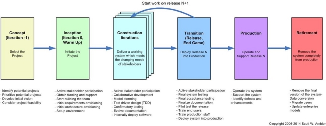
Following are the common phases of agile models
- Concept – the product is planned and will be prioritized
- Inception – the team is made; the funding has been given and the requirements will have been discussed
- Iteration or construction – the developers will work on the software based on the requirements.
- Release – Quality assurance testing, internal and external training is provided, the documents will have been developed.
- Production – in this stage there will be continuation of support for the software
- Retirement – customer notification and migration.
 Scott W. Amber
Strength and weakness of Agile Models
|
Strengths |
Weakness |
|
|
Recommendation to ASDA Suppliers: ASDA suppliers should adapt waterfall approach, as their requirements are no uncertain and completely well known. It can be easily managed because of its rigidity. ASDA suppliers does not need long term project as their all requirements are stated and water fall best suit.
Task 3:Illustrate and compare
3.1: Illustrate how the Unified Modelling Language (UML) may be deployed as part of an Object-Oriented (OO) software development project.
Class Diagrams
A class Diagram is a UML type of static structure diagram, it describes the system structure by the system classes, operations, attributes and also the relationship with the objects.
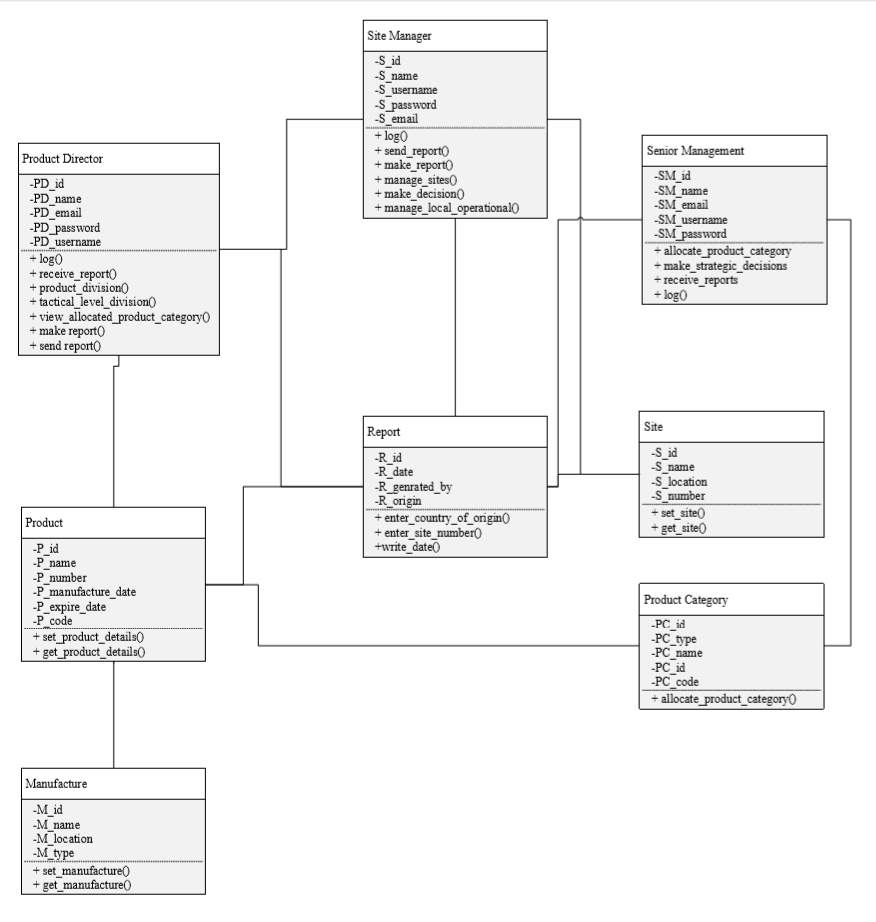
Figure 1 Class Diagram: the class diagram represents the data members and member functions of each class which will be used while developing the system. There are six classes with the names: login, headquarter, Employee, Products and Factories.
Activity Diagrams
An Active diagram is a UML that shows the active aspects of the system.
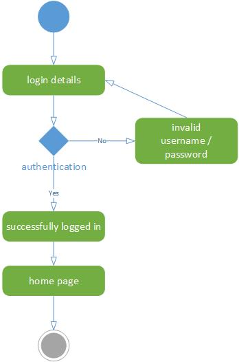
Figure 2 Activity Diagram: the activity diagram, which shows the procedure to perform a activity successfully. This activity diagram shows that how a user login. User will login into the system by providing the username and password. If the credentials are correct user will be logged in.

Figure 3 Activity diagram: This activity diagram shows how the user can place or request order. User will first login into the system by providing the username and password. If the credentials are correct user will be logged in and able to see the homepage or dashboard. System will check the availability of the product and if the product is available user can successfully place order.
Sequence Diagrams
Sequence diagrams are a UML that shows the interactions and detail of how operations are carried out.

Figure 4 Sequence diagram: this is a sequence diagram which shows the interaction of user (ADMIN) with system for the login process for Asda
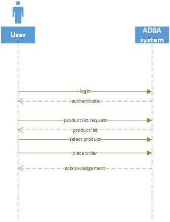
Figure 5 Sequence diagram: is a sequence diagram which shows the interaction of user with system for placing and receiving order details.

Figure 6 Sequence diagram: this is a sequence diagram which shows the interaction of user (ADMIN) with system for the process of updating product.
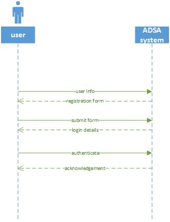
Figure 7 Sequence diagram: this is a sequence diagram which shows the interaction of user and admin with system for the registration process.

Figure 8 Sequence diagram: This sequence diagram shows procedure of the complete software product that which operations can be performed using the software. User will first login into the system by providing the username and password. If the credentials are correct user will be logged in and will be able to view dashboard. Then the user can perform operations manage product division, manage allocated division, view allocated product category, make report and receive report.
Use Case Diagrams
A Use Case Diagram is a UML that is used for graphic representation of the communication with the elements of a system.

Figure 9 Use case diagram: the above diagram is the high-level use diagram of the software which show all the possible operations that can be performed using the system for Asda
3.2: Compare and contrast two different commercial UML modelling tools that may be employed to do this work.
|
Microsoft Visio |
Rational Rose |
|
Visio is the tool developed by Microsoft used for UML modelling. It can be used for many purposes that make use of layouts, charts and diagrams. Standard images are used in Visio that can be utilized by playbooks, flow charts, network diagrams and even for decision diagrams. Microsoft Visio provide ease for teams so that they can work together and it also multiple members of team to work with collaboration. Link of tool: https://www.microsoft.com/en-us/p/visio-professional-2019/cfq7ttc0k7cg?activetab=pivot%3aoverviewtab Screen Shot:
|
Rational rose is a UML object oriented based software designing tool used for visual modelling and construction of components of enterprise-level software. Rational rose is used by the software designer to create visual model of system or software’s classes, use cases, activities and relationship among them. Rational rose is the product of IBM.S Link of tool: https://www.dataone.org/software-tools/rational-rose-0 Screen Shot:
|


Task 4: Critically evaluate two implementation languages
Sequence, selection & iteration
Sequencing: sequencing implies that the PC will run your code together, one line at any minute from the best to the base of the program. It will start at line one and at this point implement line two and the line three etc. it will do this until it achieves the last line of your program
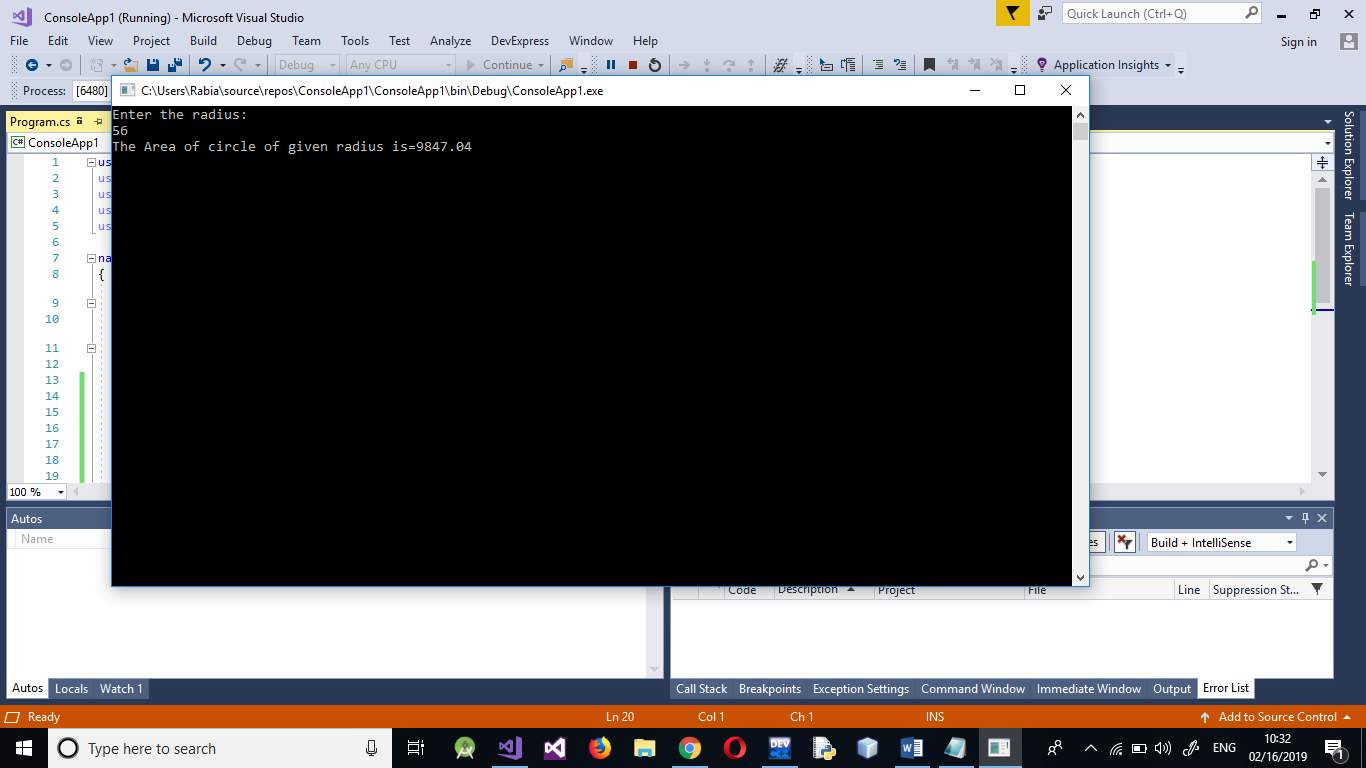
For Example, (C#):

Output:
Selection: for selection you will need a few lines of code to be running just if something goes wrong, or you will need the PC to disregard these lines and move over them. This is done by using IF explanations. For example, on the off chance that a condition is met, lines 4, 5, 6 are executed generally the PC bounces to line 7 without taking a gander at line 4,5 and 6.
For Example, (C)
Code Screen Shot
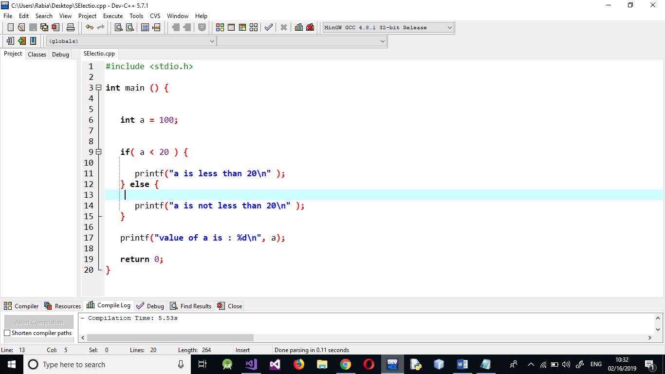
Output:

Iteration: Sometimes you need the PC to execute similar lines of code a few times. This is finished utilizing a circle. There are three kinds of circles: For circles, while circles and rehash until circles. That is helpful as it empowers you not to need to duplicate similar lines of code ordinarily.
For Example, (C)
Code Screen Shot:

Output:

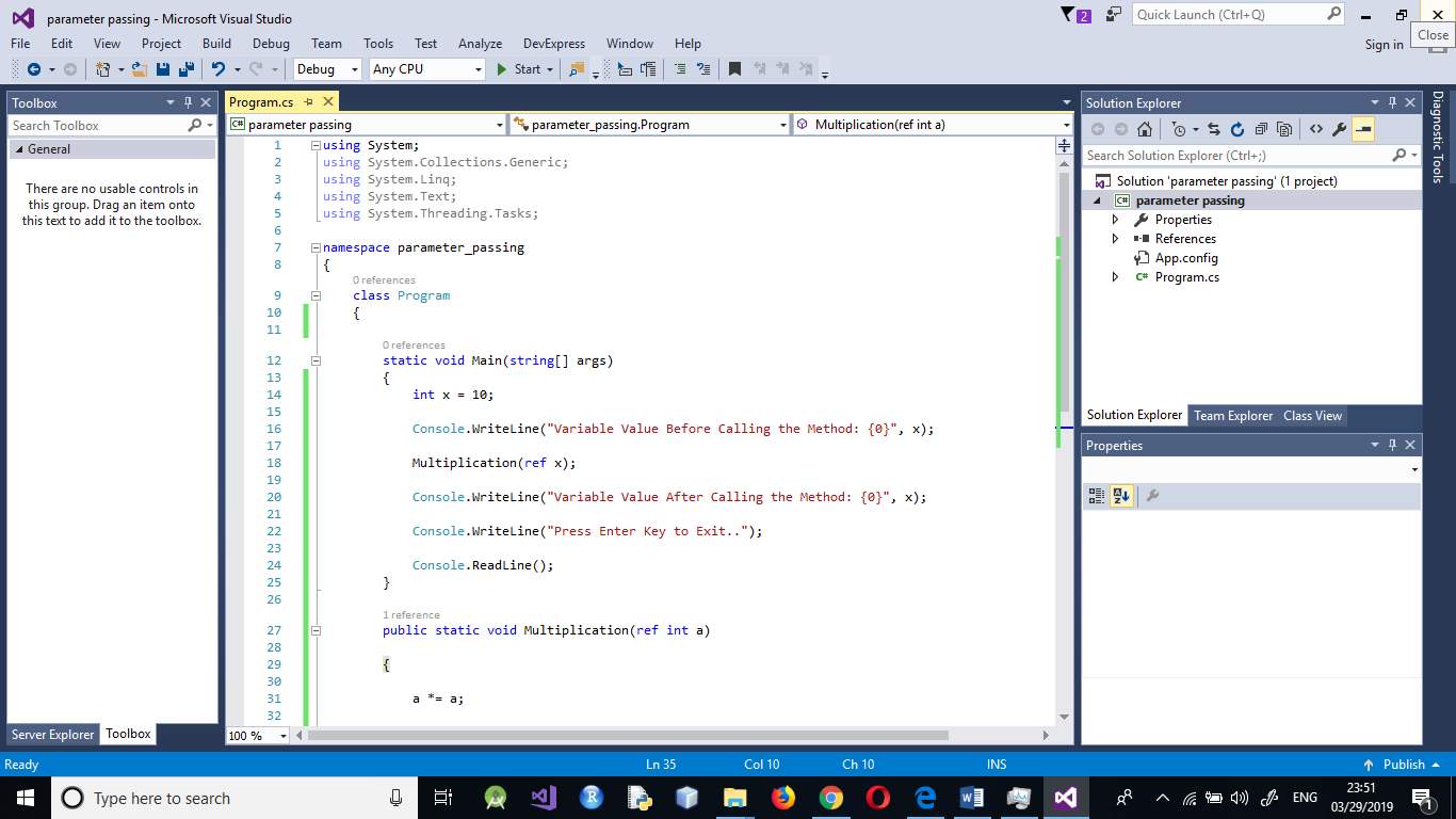
- Parameter Passing and Programming Interface
Parameter Passing:
Parameter passing technique allows to access the value of the local variable in main program and can be updated and used in more the one subprograms. Two type of parameter passing is done.
- Pass by reference
- Pass by value
For example (C).
Code:

Output:

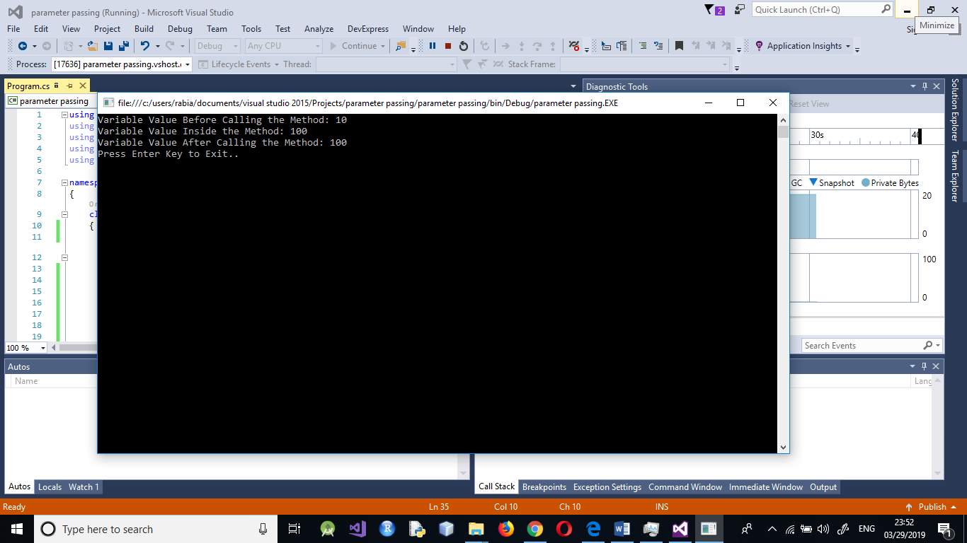
For Example(C#)
Code:
Output:
• Modularity and programming ‘units’
Modular programming computer programs is a product method that underscores separating the worth of a program into autonomous, tradable modules, to such an extent that each comprises all things required to execute just a single part of the ideal usefulness.
A module interface connects the components which are given and required by the module. The components categorised in the border are discernible by different modules. The execution covers the working code that relates to the OOP and structure programming. Measured writing computer programs is resolutely identified with planned programming and article situated programming, all having a similar objective of reassuring development of expansive programming projects and outlines by deterioration into little pieces.
References
Anon., 2016. flat world solutions. [Online]
Available at: https://blog.flatworldsolutions.com/10-differences-agile-waterfall-methodology/
[Accessed Feburary ].
Anon., 2018. [Online]
Available at: https://help.sap.com/doc/abapdocu_750_index_htm/7.50/enUS/abenformal_parameters_oview.html
[Accessed Feburary 2018].
Anon., 2018. [Online]
Available at: https://www.totalmetrics.com/consulting-function-points/software-measurement-implementation
[Accessed Feburary 2018].
Anon., 2018. [Online]
Available at: https://www.softwaretestinghelp.com/what-is-sdlc-waterfall-model/
[Accessed Feburary 2018].
Anon., 2018. [Online]
Available at: https://www.ics.uci.edu/~ziv/ooad/intro_to_se/tsld008.htm
[Accessed 2018].
Anon., 2018. https://irisiri.weebly.com/sequence-selection-and-iteration.html. [Online]
Available at: https://irisiri.weebly.com/sequence-selection-and-iteration.html
[Accessed Feburary 2018].
Cite This Work
To export a reference to this article please select a referencing stye below:
Related Services
View all


DMCA / Removal Request
If you are the original writer of this essay and no longer wish to have your work published on UKEssays.com then please:


